Drill Collar Specifications: A Guide to Making the Right Choice
Choosing the right drill collar is crucial for assembling a bottom-hole assembly (BHA) that meets operational demands. Understanding key specifications ensures optimal performance and minimizes potential issues during drilling. Drill collars are typically identified based on parameters such as:
Outer Diameter (OD)
Inner Diameter (ID)
Nominal Weight
Thread Connections
Length
Determining the Appropriate Drill Collar Size
The selection of drill collar size largely depends on the borehole diameter and the bit program. Generally, the best drill collar will have the largest possible OD and maximum wall thickness for safe operation within the borehole. This approach offers several benefits:
Fewer drill collars are needed to achieve the desired weight.
Fewer connections between drill collars reduce operational complexity.
Handling time during operations is significantly minimized.
Rigid components that fit closely help enhance bit performance.
Tight clearance reduces fatigue damage at the connections.
Additionally, the buoyant weight of the drill collar string must exceed the expected maximum bit weight by 15–20%. The neutral point, balancing tensile and compressive forces, should always lie within the drill collar string. In large-diameter boreholes, a tapered drill collar string—comprising two or more drill collar sizes—is often employed to ensure a gradual stiffness transition.
Hydraulic considerations guide the choice of drill collar ID. It must support efficient fluid circulation without causing excessive pressure drops.
Length Specifications for Drill Collars
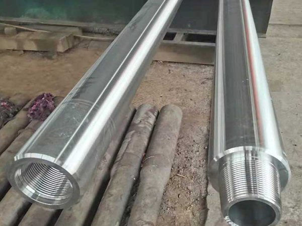
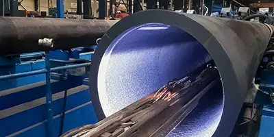
Drill collars are typically supplied in Grade 2 lengths, ranging from 30 to 32 feet. Constructed from chromium-molybdenum alloy, these drill collars undergo heat treatment along their entire length. Precision machining of the bore ensures smooth and balanced rotation, which is critical for performance.
|
Drill Collar Connection
|
Drill Collar Diameter(in)
|
Bore Diameter(in)
|
Length(ft)
|
Linear Weight (Approx.) (lb/ft)
|
Displacement (Open End) (US gal/ft)
|
Bending Strength Ratio
|
|
NC 23-31
|
3-1/8
|
1-1/4
|
30
|
22.00
|
0.337
|
2.57:1
|
|
NC 26-35 (2-3/8 IF)
|
3-1/2
|
1-1/2
|
30
|
26.70
|
0.408
|
2.42:1
|
|
NC 31-41 (2-7/8 IF)
|
4-1/8
|
2
|
30 or 31
|
33.65
|
0.515
|
2.43:1
|
|
NC35-47
|
4-3/4
|
2
|
30 or 31
|
46.81
|
0.716
|
2.58:1
|
|
NC 38-50 (3-1/2 IF)
|
5
|
2-1/4
|
30 or 31
|
53.29
|
0.815
|
2.38:1
|
|
NC 44-60
|
6
|
2-1/4
|
30 or 31
|
82.61
|
1.264
|
2.49:1
|
|
NC 44-60
|
6
|
2-13/16
|
30 or 31
|
75.90
|
1.161
|
2.84:1
|
|
NC 44-62
|
6-1/4
|
2-1/4
|
30 or 31
|
90.52
|
1.385
|
2.91:1
|
|
NC 46 -62 (4IF)
|
6-1/4
|
2-13/16
|
30 or 31
|
83.81
|
1.282
|
2.63:1
|
|
NC 46 -65 (4IF)
|
6-1/2
|
2-1/4
|
30 or 31
|
99.52
|
1.522
|
2.76:1
|
|
NC 46-65 (4IF)
|
6-1/2
|
2-13/16
|
30 or 31
|
92.81
|
1.420
|
3.05:1
|
|
NC 46-67 (4IF)
|
6-3/4
|
2-1/4
|
30 or 31
|
108.52
|
1.600
|
3.18:1
|
|
NC 50-70 (4IF)
|
7
|
2-1/4
|
30 or 31
|
117.52
|
1.798
|
2.54:1
|
|
NC 50 -70 (4IF)
|
7
|
2-13/16
|
30 or 31
|
110.77
|
1.694
|
2.73:1
|
|
NC 50-72 (4IF)
|
7-1/4
|
2-13/16
|
30 or 31
|
119.81
|
1.833
|
3.12:1
|
|
NC 56-77
|
7-3/4
|
2-13/16
|
30 or 31
|
139.90
|
2.140
|
2.70:1
|
|
NC 56-80
|
8
|
2-13/16
|
30 or 31
|
150.81
|
2.307
|
3.02:1
|
|
6-5/8 REG
|
8-1/4
|
2-13/16
|
30 or 31
|
161.81
|
2.472
|
2.93:1
|
|
NC 61-90
|
9
|
2-13/16
|
30 or 31
|
195.81
|
2.995
|
3.17:1
|
|
7-5/8 REG
|
9-1/2
|
3
|
30 or 31
|
217.00
|
3.319
|
2.81:1
|
|
NC 70 -97
|
9-3/4
|
3
|
30 or 31
|
230.00
|
3.518
|
2.57:1
|
|
NC 70-100
|
10
|
3
|
30 or 31
|
242.97
|
3.717
|
2.81:1
|
|
8-5/8 REG
|
11
|
3
|
30 or 31
|
299.00
|
4.574
|
2.84:1
|
|
API Boreback Box Connection
API stress relieve groove pin connection
Cold Rolling Thread roots
Phosphate coated connections
|
|
Spiral grooved or Non-Spiral (Slick Type)
Type of Hardband and Hardband configuration
Elevator and Slip recesses or Slip Recess only
Other type of connections to meet specific needs
|
|
Standard Pressed Steel Thread Protectors. Cast Steel Lifting Bail Thread Protectors upon request.
|
|
Issued in accordance with API 7/7-1 and API RP7G specifications.
Third Party Inspection can be performed on request at buyer’s care and expense.
|
Thread Connections on Drill Collars
Unlike
drill pipes, drill collars do not require tool joints due to their thick walls. Thread connections are directly machined onto the body of the drill collar. These threads differ from those on standard
drill pipe tool joints. Correct torque application is essential to prevent connection failure, as the threaded sections represent the weakest points in the drill collar assembly.
While most drill collars feature smooth, circular external surfaces, alternative profiles are also available for specific operational needs.
Conclusion
Understanding the specifications of
drill collars allows for an informed selection process that ensures operational efficiency and safety. Choosing the right size, length, and connections for your application reduces downtime, improves bit performance, and minimizes fatigue risks. Always consider hydraulic, weight, and stiffness factors when planning the bottom-hole assembly to achieve the best results.


 English
 Español
 بالعربية







 Phone :
  Whatsapp :
  Email :


