Casing and Tubing

Casing and Tubing

The American Petroleum Institute (API) and the International Organization for Standardization (ISO) have established two basic types of pipes used for exploration and production in the oil and gas industry: casing and tubing. Casing and Tubing also known as OCTG. Casing and tubing strings are the main parts of the well construction. All wells drilled for the purpose of oil or gas production (or injecting materials into underground formations) must be cased with material with sufficient strength and functionality. Well casing  pipe is a pipe used in oil, gas, or water wells to protect the well walls and stabilize the wellbore.Casing pipe is used to line the drilled borehole that is being utilized for oil extraction. Similar to drill pipes, oil well casing pipe  is also subjected to axial tension and therefore needs to be made from high-quality, strong steel. Casing (well  pipe casing) is a large-diameter pipe fixed in the borehole using cement.Tubing is the pipe used after drilling is completed to transport crude oil and natural gas from the oil or gas reservoir to the surface.

Sizes of Casing and Tubing

Diameter :from 4 1/2 inch  to 20 inch  (48.26mm - 508mm) ( Casing)
Size: OD: 48.26mm-114.3mm ( Tubing)
Nominal Weight: from 9.5 lb/ft  to 169 lb/ft, from 9.5 ppf  to 169 ppf
Lenght: R1, R2, R3

Types of Casing and Tubing

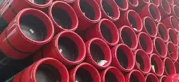
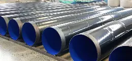
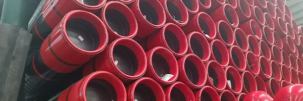
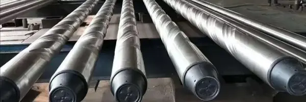
Casing pipes are steel pipes used to support oil and gas wells, ensuring normal operation during drilling and after well completion. Each well requires multiple layers of casing depending on the drilling depth and geological conditions. Once the casing is lowered into the well, it must be cemented in place. Unlike tubing and 
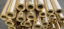
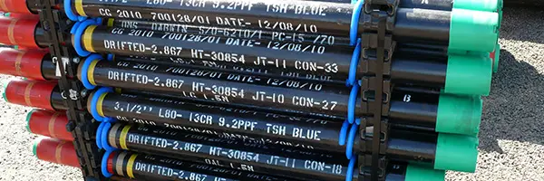
drill pipes, casings are not reusable and are considered consumable materials. Consequently, casings account for more than 70% of the total consumption of an oil well. Casing types include seamless casing pipe(small and medium diameters), ERW casing pipe (medium diameter), 
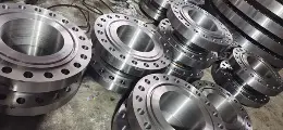
casing pup joints, and casing couplings. Based on their purpose, casings are categorized as conductor casing pipe, surface casing pipe, intermediate casing pipe, and production casing pipe.


Oil well pipe casing pipes are further classified as follows:

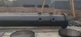
Conductor Casing pipe: The first barrier between the surface and the underground. It helps prevent well collapse and groundwater contamination, and most importantly, provides structural support. Conductor casings are installed at the surface by drilling or driving. Their sizes range from 18 to 36 inches.

Surface Casing pipe: Primarily used for environmental protection and safety. It helps isolate freshwater zones, prevent blowouts, and supports the wellhead and blowout preventer (BOP) equipment. Therefore, surface casings must meet very high safety standards. They support the next casing string. The size can vary depending on the application, but the most common surface casing size is 13 3/8 inches.

Intermediate Casing pipe: Not required for all types of oil and gas production. If used, it is placed between the surface casing and the production casing. Sizes range from 13 3/8 to 16 inches.

Production Casing pipe: Provides structural integrity and pressure control for the hydrocarbon-bearing sections, mainly used during oil production.

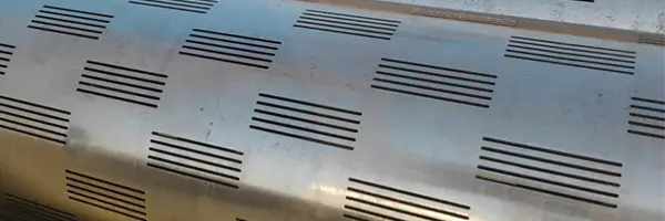
Production Liner: Can be hung from the production casing pipe or one of the previous casing pipes. Liners help significantly reduce costs as they do not need to extend the entire depth of the well. They can be pre-perforated to save time and costs.


Grades of Casing and Tubing

API 5CT H40
API 5CT J55
API 5CT K55
API 5CT M65
API 5CT N80 (1,Q)
API 5CT L80 (9Cr,13Cr)
API 5CT C90
API 5CT T95
API 5CT P110
API 5CT Q125

Application of Casing and Tubing

Casing and tubing are essential oil drilling equipment with various functions such as sealing perforations, supporting wellbore walls, preventing formation collapse, and controlling well flow. Casing and tubing are widely used in petroleum exploration, extraction, and transportation. During the exploration phase, casing and tubing are used to obtain geological samples and assess the properties of underground oil reservoirs. In the extraction phase, casing supports the wellbore walls, prevents wellbore collapse, and controls well flow. In the transportation phase, tubing is used to transport oil and natural gas.


Well  pipe casing is subject to external pressure from the surrounding rock and internal pressure during oil production, so it needs to withstand high axial tension. During the drilling process, good well  pipe casing is very useful in the following aspects:
Fixes the drill string to prevent the collapse of unstable upper formations
Helps prevent contamination of the well area
Provides a uniform inner hole for easy installation of production equipment
Helps prevent contamination of the production area
Helps prevent liquid (oil) loss
Helps isolate the high-pressure area from the surface

Connections of Casing and Tubing

SC: Short round thread casing
LC: Long round thread casing
BC: Buttress thread casing
NU: Non-upset tubing
EU: External upset tubing
IJ: Integral tubing connections

Colour Code of Casing and Tubing

Grade Colour Code Pipe
Heat Treatment

Characteristics and
Recommendation

J55


Normalized, Normalized and Tempered or quenched and Tempered
Tubing & Casing for general service

K55


Normalized, Normalized and Tempered or quenched and Tempered
Casing for general service

N80 Type 1


Normalized or Normalized and Tempered
Tubing & Casing for general service

N80 Type Q


Quenched and Tempered
Tubing & Casing for general service

L80 Type 1


Quenched and Tempered
Tubing & Casing with controlled yield range for sour well service

L80 9 Cr


Quenched and Tempered
Tubing & Casing for oil & gas wells affected by CO2 corrosion

L80 13 Cr


Quenched and Tempered
Tubing & Casing for oil & gas wells affected by CO2 corrosion

C90 Type 1


Quenched and Tempered
Hight strength Tubing & Casing with controlled yield range for service in hydrogen sulphide environments

R95


Quenched and Tempered
High strength Tubing & Casing with conntrolled yield range

T95 Type 1


Quenched and Tempered
High strength Tubing & Casing with controlled yield range for service in hydrogen sulphide environments

C110


Quenched and Tempered
High strength Casing with controlled yield range for service in hydrogen sulphide environments
P110

Quenched and Tempered
High strength Tubing & Casing for high pressure service
Q125 Type 1

Quenched and Tempered
Casing for deep well service


What is casing pipe ?

Casing  pipe is a series of steel pipes that are inserted into a drilled well to stabilize the well, prevent contaminants and water from entering the oil flow, and prevent oil from seeping into the groundwater. Casing  pipe is installed in layers with decreasing diameters and connected together to form a casing string. There are five types of casing strings: conductor, surface casing, intermediate casing, casing liner, and production casing. Steel casing pipe has a smooth wall and a minimum yield strength of 35,000 psi.Casing is used for lining the complete borehole which has been dug into the ground to procure oil.  Casing is large diameter pipe which is held in place in the borehole using cement. The diameters of casing pipe range from 4.5″ to 36″.

What is tubing pipe ?

Tubing pipe is inserted inside the wellbore through the oil well casing pipe, which helps the transportation of the hydrocarbons to the surface. It is pipe either used for transporting natural gas or crude oil to the facilities for further processing after the drilling is complete. Tubing is available in various sizes ranging from ¾” to 4 ½”.Tubing pipe is the pipe that carries oil and gas from the producing formation to the on-site surface facilities for processing. Tubing must be strong enough to resist the loads and deformations associated with production and well repair. In addition, the size of the tubing must be able to support the expected oil and gas production rate. Obviously, tubing that is too small will limit production and the subsequent economic performance of the well. However, tubing that is too large can have economic impacts beyond the cost of the tubing string itself, because tubing size affects the overall casing design of the well.

Manufacturing Process of Casing and Tubing

API Casing and Tubing Chart

Dimensions table for tubing
DN O. D. Weight W. T. End Machining Form
Steel Grade
Inch mm lb/ft kg/m Inch mm H40 J55 L80 N80 C90 P110
K55 T95
4 1/2 4.5 114.3 9.5 14.14 0.205 5.21 PS PS
10.5 15.63 0.224 5.69 PSB
11.6 17.26 0.25 6.35 PSLB PLB PLB PLB PLB
13.5 20.09 0.29 7.37 PLB PLB PLB PLB
15.1 22.47 0.337 9.56 PLB
5 5 127 11.5 17.11 0.22 5.59 PS
13 19.35 0.253 6.43 PSLB
15 22.32 0.296 7.52 PSLB PLB PLB PLBE PLB
18 26.79 0.362 9.19 PLB PLB PLBE PLB
21.4 31.85 0.437 11.1 PLB PLB PLB PLB
23.2 34.53 0.478 12.14 PLB
24.1 35.86 0.5 12.7 PLB
5 1/2 5.5 139.7 14 20.83 0.244 6.2 PS PS
15.5 23.07 0.275 6.98 PSLB
17 25.3 0.304 7.72 PSLB PLB PLB PLBE PLB
20 29.76 0.361 9.17 PLB PLB PLBE PLB
23 34.23 0.415 10.54 PLB PLB PLBE PLB
26.8 39.88 0.5 12.7
29.7 44.2 0.562 14.27
32.6 48.51 0.625 15.88
35.3 52.53 0.687 17.45
38 56.55 0.75 19.05
40.5 60.27 0.812 20.62
43.1 64.14 0.875 22.22
6 5/8 6.625 168.28 20 29.76 0.288 7.32 PS PSLB
24 35.72 0.352 8.94 PSLB PLB PLB PLBE PLB
28 41.67 0.417 10.59 PLB PLB PLBE PLB
32 47.62 0.475 12.06 PLB PLB PLBE PLB
7 7 177.8 17 25.3 0.231 5.87 PS
20 29.76 0.272 6.91 PS PS
23 34.23 0.317 8.05 PSLB PLB PLB PLBE
26 38.69 0.362 9.19 PSLB PLB PLB PLBE PLB
29 43.16 0.408 10.36 PLB PLB PLBE PLB
32 47.62 0.453 11.51 PLB PLB PLBE PLB
35 52.09 0.498 12.65 PLB PLB PLBE PLB
38 56.55 0.54 13.72 PLB PLB PLBE PLB
42.7 63.54 0.625 15.88
46.4 69.05 0.687 17.45
50.1 74.56 0.75 19.05
53.6 79.77 0.812 20.62
57.1 84.97 0.875 22.22
7 5/8 7.625 193.68 24 35.72 0.3 7.62 PS
26.4 39.29 0.328 8.33 PSLB PLB PLB PLBE PLB
29.7 44.2 0.375 9.52 PLB PLB PLBE PLB
33.7 50.15 0.43 10.92 PLB PLB PLBE PLB
39 58.05 0.5 12.7 PLB PLB PLBE PLB
42.8 63.69 0.562 14.27 PLB PLB PLB PLB
45.3 67.41 0.595 15.11 PLB PLB PLB PLB
47.1 70.09 0.625 15.88 PLB PLB PLB PLB
51.2 76.19 0.687 17.45
55.3 80.3 0.75 19.05
8 5/8 8.625 219.08 24 35.72 0.264 6.71 PS
28 41.62 0.304 7.72 PS
32 47.62 0.352 8.94 PS PSLB
36 53.57 0.4 10.16 PSLB PLB PLB PLBE PLB
40 59.53 0.45 11.43 PLB PLB PLBE PLB
44 65.48 0.5 12.7 PLB PLB PLBE PLB
49 72.92 0.557 14.15 PLB PLB PLBE PLB
9 5/8 9.625 244.48 32.3 48.07 0.312 7.92 PS
36 53.57 0.352 8.94 PS PSLB
40 59.53 0.395 10.03 PSLB PLB PLB PLBE
43.5 64.73 0.435 11.05 PLB PLB PLBE PLB
47 69.94 0.472 11.99 PLB PLB PLBE PLB
53.5 79.62 0.545 13.84 PLB PLB PLBE PLB
58.4 86.91 0.595 15.11 PLB PLB PLB PLB
59.4 88.4 0.609 15.47
64.9 96.58 0.672 17.07
70.3 104.62 0.734 18.64
75.6 112.5 0.797 20.24
10 3/4 10.75 273.05 32.75 48.74 0.279 7.09 PS
40.5 60.27 0.35 8.89 PS PSB
15.5 67.71 0.4 10.16 PSB
51 75.9 0.45 11.43 PSB PSB PSB PSBE PSB
55.5 82.59 0.495 12.57 PSB PSB PSBE PSB
60.7 90.33 0.545 13.84 PSBE PSB
65.7 97.77 0.595 15.11 PSB PSB
73.2 108.93 0.672 17.07
79.2 117.86 0.734 18.64
85.3 126.94 0.797 20.24
11 3/4 11.75 42 62.5 0.333 8.46 PS
47 69.94 0.375 20.24
54 80.36 0.435 8.46
60 89.29 0.489 9.53
65 96.73 0.534 11.05
71 105.66 0.582 14.42
13 3/8 13.375 339.73 48 71.43 0.33 8.38 PS
54.5 81.1 0.38 9.65 PSB
61 90.78 0.43 10.92 PSB
68 101.19 0.48 12.19 PSB PSB PSB PSB PSB
72 107.15 0.514 13.06 PSB PSB PSB PSB
16 16 406.4 65 96.73 0.375 9.53 PS
75 111.61 0.438 11.13 PSB
84 125.01 0.495 12.57 PSB
109 162.21 0.656 16.66 P P P P
18 5/8 18.625 473.08 87.5 130.21 0.435 11.05 PS PSB
20 20 508 94 139.89 0.438 11.13 PSL PSLB
106.5 158.49 0.5 12.7 PSLB
133 197.93 0.635 16.13 PSLB
P——Plain;S——Short-thread;L——Long-thread;B——Buttress thread;E——Extreme thread


Dimensions table for casing

DN O. D. Weight W. T. End Machining Form
Steel Grade
Inch mm lb/ft kg/m Inch mm H40 J55 L80 N80 C90 P110
K55 T95
4 1/2 4.5 114.3 9.5 14.14 0.205 5.21 PS PS
10.5 15.63 0.224 5.69 PSB
11.6 17.26 0.25 6.35 PSLB PLB PLB PLB PLB
13.5 20.09 0.29 7.37 PLB PLB PLB PLB
15.1 22.47 0.337 9.56 PLB
5 5 127 11.5 17.11 0.22 5.59 PS
13 19.35 0.253 6.43 PSLB
15 22.32 0.296 7.52 PSLB PLB PLB PLBE PLB
18 26.79 0.362 9.19 PLB PLB PLBE PLB
21.4 31.85 0.437 11.1 PLB PLB PLB PLB
23.2 34.53 0.478 12.14 PLB
24.1 35.86 0.5 12.7 PLB
5 1/2 5.5 139.7 14 20.83 0.244 6.2 PS PS
15.5 23.07 0.275 6.98 PSLB
17 25.3 0.304 7.72 PSLB PLB PLB PLBE PLB
20 29.76 0.361 9.17 PLB PLB PLBE PLB
23 34.23 0.415 10.54 PLB PLB PLBE PLB
26.8 39.88 0.5 12.7
29.7 44.2 0.562 14.27
32.6 48.51 0.625 15.88
35.3 52.53 0.687 17.45
38 56.55 0.75 19.05
40.5 60.27 0.812 20.62
43.1 64.14 0.875 22.22
6 5/8 6.625 168.28 20 29.76 0.288 7.32 PS PSLB
24 35.72 0.352 8.94 PSLB PLB PLB PLBE PLB
28 41.67 0.417 10.59 PLB PLB PLBE PLB
32 47.62 0.475 12.06 PLB PLB PLBE PLB
7 7 177.8 17 25.3 0.231 5.87 PS
20 29.76 0.272 6.91 PS PS
23 34.23 0.317 8.05 PSLB PLB PLB PLBE
26 38.69 0.362 9.19 PSLB PLB PLB PLBE PLB
29 43.16 0.408 10.36 PLB PLB PLBE PLB
32 47.62 0.453 11.51 PLB PLB PLBE PLB
35 52.09 0.498 12.65 PLB PLB PLBE PLB
38 56.55 0.54 13.72 PLB PLB PLBE PLB
42.7 63.54 0.625 15.88
46.4 69.05 0.687 17.45
50.1 74.56 0.75 19.05
53.6 79.77 0.812 20.62
57.1 84.97 0.875 22.22
7 5/8 7.625 193.68 24 35.72 0.3 7.62 PS
26.4 39.29 0.328 8.33 PSLB PLB PLB PLBE PLB
29.7 44.2 0.375 9.52 PLB PLB PLBE PLB
33.7 50.15 0.43 10.92 PLB PLB PLBE PLB
39 58.05 0.5 12.7 PLB PLB PLBE PLB
42.8 63.69 0.562 14.27 PLB PLB PLB PLB
45.3 67.41 0.595 15.11 PLB PLB PLB PLB
47.1 70.09 0.625 15.88 PLB PLB PLB PLB
51.2 76.19 0.687 17.45
55.3 80.3 0.75 19.05
8 5/8 8.625 219.08 24 35.72 0.264 6.71 PS
28 41.62 0.304 7.72 PS
32 47.62 0.352 8.94 PS PSLB
36 53.57 0.4 10.16 PSLB PLB PLB PLBE PLB
40 59.53 0.45 11.43 PLB PLB PLBE PLB
44 65.48 0.5 12.7 PLB PLB PLBE PLB
49 72.92 0.557 14.15 PLB PLB PLBE PLB
9 5/8 9.625 244.48 32.3 48.07 0.312 7.92 PS
36 53.57 0.352 8.94 PS PSLB
40 59.53 0.395 10.03 PSLB PLB PLB PLBE
43.5 64.73 0.435 11.05 PLB PLB PLBE PLB
47 69.94 0.472 11.99 PLB PLB PLBE PLB
53.5 79.62 0.545 13.84 PLB PLB PLBE PLB
58.4 86.91 0.595 15.11 PLB PLB PLB PLB
59.4 88.4 0.609 15.47
64.9 96.58 0.672 17.07
70.3 104.62 0.734 18.64
75.6 112.5 0.797 20.24
10 3/4 10.75 273.05 32.75 48.74 0.279 7.09 PS
40.5 60.27 0.35 8.89 PS PSB
15.5 67.71 0.4 10.16 PSB
51 75.9 0.45 11.43 PSB PSB PSB PSBE PSB
55.5 82.59 0.495 12.57 PSB PSB PSBE PSB
60.7 90.33 0.545 13.84 PSBE PSB
65.7 97.77 0.595 15.11 PSB PSB
73.2 108.93 0.672 17.07
79.2 117.86 0.734 18.64
85.3 126.94 0.797 20.24
11 3/4 11.75 42 62.5 0.333 8.46 PS
47 69.94 0.375 20.24
54 80.36 0.435 8.46
60 89.29 0.489 9.53
65 96.73 0.534 11.05
71 105.66 0.582 14.42
13 3/8 13.375 339.73 48 71.43 0.33 8.38 PS
54.5 81.1 0.38 9.65 PSB
61 90.78 0.43 10.92 PSB
68 101.19 0.48 12.19 PSB PSB PSB PSB PSB
72 107.15 0.514 13.06 PSB PSB PSB PSB
16 16 406.4 65 96.73 0.375 9.53 PS
75 111.61 0.438 11.13 PSB
84 125.01 0.495 12.57 PSB
109 162.21 0.656 16.66 P P P P
18 5/8 18.625 473.08 87.5 130.21 0.435 11.05 PS PSB
20 20 508 94 139.89 0.438 11.13 PSL PSLB
106.5 158.49 0.5 12.7 PSLB
133 197.93 0.635 16.13 PSLB
P——Plain;S——Short-thread;L——Long-thread;B——Buttress thread;E——Extreme thread


Our casing and tubing are not only manufactured strictly in accordance with API standards, but we also develop proprietary grades for special application environments such as sour, high collapse, chrome and CRA. With these proprietary grades, we are able to provide the best solution for each customer's specific well conditions. All of our products are produced in accordance with the most stringent quality standards. Our operations have been globally ISO 9001 certified, implement a unified quality policy, and adopt a rigorous quality management system. If you need customized oil casing, choose us baowisteel and we will provide you with satisfactory service.


Recommended Products

We use cookies to offer a better browsing experience, analyze site traffic, and personalize content. By using this site, you agree to our use of cookies.

Accept
Decline