What are oil well casing and tubing?
Oil well casing and tubing are indispensable special pipes in oil and gas drilling and production operations, and constitute the "lifeline" of oil and gas wells. As the core components for supporting the well wall and conveying fluids, they play an irreplaceable role in the entire oil and gas field development cycle. Oil well casing is a steel pipe used to support the well wall of oil and gas wells to ensure the normal operation of the entire oil well during the drilling process and after completion; while tubing is a pipeline installed in the casing to transport oil and gas from the formation to the ground. Although these two types of pipes have different functions, they together constitute the channel system for oil and gas production, and their performance and quality directly affect the safety, production efficiency and life of oil and gas wells.
In the oil industry, the consumption of casing and tubing is huge. According to statistics, about 62 kilograms of oil well pipes are required for drilling 1 meter of well depth, of which casing accounts for 48 kilograms and tubing accounts for 10 kilograms. Casing is a disposable consumable material. After going down the well, cement is required for cementing and cannot be reused. Therefore, its consumption accounts for more than 70% of all oil well pipes. In contrast, oil pipes can be reused in theory, but in practice they are generally used no more than three times and must be replaced in a timely manner if problems arise.

Definition of oil casing and oil tubing
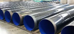
Oil casing: As a "solid barrier" to protect oil wells, oil casing is mainly used to go down from the surface into the drilled wellbore as a lining. Under complex geological conditions, it shoulders the important task of fixing the oil and gas well wall or wellbore. For example, in loose sandstone layers, oil casing can prevent the well wall from collapsing and ensure the smooth progress of drilling operations; in high-pressure oil and gas layers, it can withstand huge formation pressure and ensure the safe storage and exploitation of oil and gas. Its stable structure and reliable performance are the basis for maintaining the long-term stable operation of oil wells.
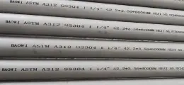
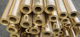
Oil tubing: It can be called the "high-speed channel" for oil and gas transportation. The oil pipe is mainly used to go down into the well as a pipe for producing or injecting liquid. After drilling is completed, it becomes a key channel for transporting crude oil and natural gas from the oil and gas layer to the surface. Whether it is light crude oil or high-viscosity heavy oil, the oil pipe can efficiently transport it to the ground, providing a guarantee for subsequent processing and utilization. In oil fields developed by water injection, oil pipelines are also responsible for injecting high-pressure water into the formation to maintain formation pressure and increase crude oil recovery.
Casing and tubing dimensions
|
Item
|
Casing
|
Tubing
|
|
Outer Diameter Range
|
114.3 mm (4-1/2") to 508 mm (20")
|
60.3 mm (2-3/8") to 114.3 mm (4-1/2")
|
|
Length Specifications
|
- R-1: 4.88 – 7.62 m - R-2: 7.62 – 10.36 m - R-3: >10.36 m
|
Typically 6 – 10 m
|
|
Standard Sizes (OD)
|
Common production casing: 139.7 mm (5-1/2")
|
Common tubing sizes: - 60.3 mm (2-3/8") - 73.0 mm (2-7/8") - 88.9 mm (3-1/2") - 114.3 mm (4-1/2")
|
|
Wall Thickness (example)
|
7.72 – 9.17 mm for 139.7 mm casing
|
Varies by size and application
|
|
Design Considerations
|
- Casing is selected from inner to outer layers - Ensures annular clearance for cementing
|
- Designed based on output, flow rate, and lifting efficiency
|
|
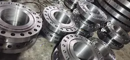
Connection Type
|
Threaded connections
|
Threaded connections
|
|
Application Focus
|
Structural integrity and zonal isolation
|
Production flow path inside casing
|
What are the roles of tubing and casing in oil wells? Which casing can be categorized according to the different roles?
In oilfield drilling and production operations, "casing" refers to the tubing used as a liner in the borehole to prevent the well wall from flowing or caving in. It is a permanent part of the well and is cemented to the bottom of the casing. The cement is sometimes returned to the surface. Most casing has an outside diameter of 114.3mm or larger sizes. The innermost tube in the well is called tubing. Downhole fluids are sent to the surface through the tubing, which can be separated from the casing by a production separator.The tubing is often pumped out of the well and sometimes needs to be replaced. Most tubing is 114.3mm OD or smaller.
The drilling environment often requires several layers of casing to achieve the desired total well depth. Each layer of casing is further categorized according to its role:
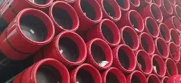
(1) Conduit. This is the outermost layer of the well, and its main purpose is to reinforce the walls of the well to prevent the surface gravel layer and uncemented rock from falling into the well.
(2) Structural pipe. Between the conduit and the surface tubing, the purpose of this layer of casing includes addressing recurrent leakage or well collapse and minimizing shallow gas surges.
(3) Surface casing. The purpose of the lower surface casing is multiple and includes isolating the freshwater layer to prevent collapse and leakage, isolating weak sections of the layer that cannot withstand the back pressure exerted as a result of well surge control, providing for the installation of a blowout preventer, and supporting the weight of all layers of casing smaller than the surface casing.
(4) Intermediate casing. The main use is because high pressure layers will be encountered in drilling, and high density drilling fluid is needed to control the abnormally high pressure, and the shallower weak strata must be protected against leakage or stuck drilling. In some special cases, intermediate casing is also used to isolate salt formations or expansive and collapse-prone shale formations.
(5) Lining pipe. The liner pipe serves the same purpose as the intermediate casing. The liner pipe extends upward from the bottom of the well into the intermediate casing, but does not extend to the surface. Liner tubing is often used to save money by not having to extend the tubing column to the surface but still achieve the purpose of controlling pressure and fracture gradients.
(6) Production casing. Also known as formation casing. The role of this column is: to separate the production layer from other formations, forming a given diameter and can go down to the production layer of the working wellbore, to protect the production tubing and equipment.
(7) Recovery tubing column. The liner is also commonly used as part of the production casing rather than as a separate column of pipe from the surface down to the production formation. The liner can be returned to the surface with an appropriate amount of tubing from the top of the liner.
What are the steel grades of tubing and casing and what do they mean?
In the API SPEC5CT standard, the steel grade of casing and tubing indicates its yield strength and some special characteristics. Steel grade designations are usually expressed as 1 letter and 2 or 3 numbers, such as N80. in most cases, the further down the alphabet the letters go, the greater the yield strength of the pipe. For example, N80 grade steel has a greater yield strength than J55.
The numerical notation is determined by the minimum yield strength of the pipe expressed in thousands of pounds per square inch. For example, the minimum yield strength of N80 steel grade is 550Mpa.
API SPEC5 CT standard lists the following casing steel grades: H40, J55, K55, N80, M65, L80, C90, C95, T59, P110, Q125; casing steel grades are: H40, J55, N80, L80, C90, T59, P110.
J55/K55: Basic steel grade, minimum yield strength 379MPa (55,000psi), suitable for shallow wells and low-pressure wells
N80: Divided into two categories, N80-1 and N80Q, minimum yield strength 552MPa (80,000psi), widely used in medium and deep wells
L80: Including L80-1, L80-9Cr and L80-13Cr, minimum yield strength 552MPa, with better corrosion resistance
P110: High-strength steel grade, minimum yield strength 758MPa (11 0,000psi), used in deep wells and high-pressure wells
Q125: divided into Q125-1, Q125-2, Q125-3 and Q125-4, minimum yield strength 862MPa (125,000psi)
V150: non-API high-strength steel grade, minimum yield strength 1034MPa (150,000psi), used in ultra-deep wells and extreme conditions
It is worth noting that although the yield strength of J55 and K55 belongs to the same level, the tensile strength of K55 is higher than that of J55, reflecting the difference in material composition and processing technology. H40, as the lowest steel grade, has basically withdrawn from the market, and higher-strength special steel grades such as SM-155G (155,000psi) are also developing

 English
 Español
 بالعربية
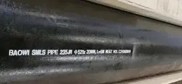
 Phone :
  Whatsapp :
  Email :


