Selecting the right casing and tubing sizes requires matching production requirements with wellbore dimensions and downhole equipment. Tubing size should be chosen based on expected flow rate, pressure, fluid properties, and artificial lift requirements. The production casing must then provide sufficient internal clearance for the tubing, couplings, and completion tools. Both sizes should be checked for mechanical strength, operating conditions, and API 5CT requirements.
1. Understand the Difference Between Casing and Tubing Sizes
Casing and tubing are both oil country tubular goods (
OCTG), but they perform different functions in a well.
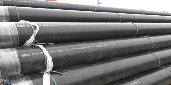
Casing is installed and cemented in stages to support the wellbore and isolate formations. Common types include conductor, surface, intermediate, and production casing, with typical outer diameters ranging from 4½″ to 20″. Casing is specified by OD and weight per foot. Heavier casing has thicker walls and greater strength but a smaller internal diameter, which affects tubing and tool clearance.
Tubing is installed inside the production casing as the main production conduit. Common sizes range from 1.900″ to 4½″ OD. Its size depends on flow requirements, downhole equipment, and artificial lift methods. Sufficient clearance must also be maintained for tubing connections, packers, and annular operations such as gas lift.
|
Comparison
|
Casing
|
Tubing
|
|
Main function
|
Wellbore support and formation isolation
|
Fluid production and injection
|
|
Installation
|
Run during drilling and usually cemented
|
Installed inside production casing
|
|
Main dimensional concern
|
Outside diameter, wall thickness, weight, drift diameter
|
Outside diameter, inside diameter, connection type
|
|
Typical applications
|
Surface, intermediate, and production strings
|
Natural flow, artificial lift, and injection
|
|
Replacement
|
Usually difficult to replace
|
Can generally be retrieved
|
|
Common standard
|
API 5CT
|
API 5CT
|
Casing and tubing sizes must be evaluated together because the outside diameter of the tubing, including its connections and associated equipment, must fit inside the available casing clearance.
2. Common Casing and Tubing Sizes Used in Oil Wells
API 5CT covers standardized dimensions, weights, grades, and product requirements for casing and tubing. Several nominal sizes are commonly encountered in oil and gas completion designs.
The following table provides a general reference. These are common nominal outside diameters, not universal recommendations for every well.
Common Casing Sizes
|
Casing OD
|
Metric Equivalent
|
Typical Application
|
|
4-1/2 in
|
114.3 mm
|
Production casing and liners
|
|
5 in
|
127.0 mm
|
Production casing
|
|
5-1/2 in
|
139.7 mm
|
Production casing
|
|
7 in
|
177.8 mm
|
Production casing and intermediate strings
|
|
7-5/8 in
|
193.7 mm
|
Intermediate casing
|
|
9-5/8 in
|
244.5 mm
|
Surface, intermediate, or production casing
|
|
10-3/4 in
|
273.1 mm
|
Surface and intermediate casing
|
|
13-3/8 in
|
339.7 mm
|
Surface casing
|
|
20 in
|
508.0 mm
|
Conductor or large surface casing
|
Common Tubing Sizes
|
Tubing OD
|
Metric Equivalent
|
Typical Application
|
|
1.900 in
|
48.26 mm
|
Small-diameter production and special applications
|
|
2-3/8 in
|
60.3 mm
|
Low-to-moderate production rates
|
|
2-7/8 in
|
73.0 mm
|
Common production tubing
|
|
3-1/2 in
|
88.9 mm
|
Higher production capacity and artificial lift
|
|
4-1/2 in
|
114.3 mm
|
Large-capacity production and specialized completions
|
The appropriate tubing size depends on the expected flow rate, fluid properties, production pressure, and downhole equipment. A larger nominal diameter does not automatically provide better production performance.
For exact dimensions, including wall thickness, nominal weight, and drift diameter, consult the applicable API 5CT dimensional tables.
3. How to Match Tubing Size with Production Casing
The compatibility between tubing and production casing is one of the most important considerations in completion design.
The tubing must fit inside the production casing with sufficient clearance for its connections, packers, artificial lift equipment, and other downhole components.
A basic dimensional relationship is:
Available casing clearance must be greater than the maximum outside diameter of the component being run into the well.
This means engineers should not compare only the nominal tubing OD with the nominal casing ID.
Example of Casing and Tubing Compatibility
A 7-inch production casing may be considered for a completion using 2-7/8-inch or 3-1/2-inch tubing.
However, neither combination should be approved based on nominal diameters alone.
The engineering team must verify the actual casing drift diameter against the tubing coupling, packer, and other completion equipment dimensions. The connection type and equipment configuration can change the available clearance.
The same principle applies to 5-1/2-inch and 4-1/2-inch production casing.
4. Select Tubing Size Based on Production Requirements
Tubing diameter directly affects fluid velocity, frictional pressure loss, and production stability.
A tubing string that is too small may create excessive pressure loss and restrict production. A tubing string that is too large may result in insufficient fluid velocity, particularly in low-rate gas wells.
The correct size should be evaluated against the well's expected production profile rather than selected solely from common industry practice.
4.1 Oil Wells and Natural Flow
For naturally flowing oil wells, tubing size should be evaluated using reservoir inflow performance and tubing outflow performance.
The main considerations include:
Expected oil and water production rates.
Reservoir pressure and flowing bottomhole pressure.
Fluid density and viscosity.
Gas-liquid ratio.
Tubing friction losses.
Required wellhead pressure.
Node analysis can help compare different tubing diameters and identify an operating point that satisfies production requirements.
Smaller tubing may increase fluid velocity but also increase frictional pressure losses. Larger tubing generally reduces friction at comparable flow conditions but may perform poorly when production rates are low.
The objective is to find a tubing diameter that balances flow efficiency and stable production.
4.2 Gas Wells and Liquid Loading
Gas wells require particular attention to tubing diameter because of liquid loading.
When gas velocity becomes insufficient to carry water and condensate to the surface, liquids accumulate in the wellbore. This increases backpressure and may significantly reduce gas production.
Smaller tubing can increase gas velocity at a given production rate and help delay liquid loading. However, an excessively small diameter creates higher frictional pressure losses and may restrict high-rate production.
Tubing selection should therefore consider:
Expected gas production during early and late production stages.
Critical liquid-carrying velocity.
Wellhead and bottomhole pressure.
Water production and condensate behavior.
Frictional pressure losses across the tubing string.
For mature gas wells, smaller-diameter velocity tubing or coiled tubing may be considered as a later production optimization measure.
The final tubing diameter should be checked using an appropriate multiphase-flow and liquid-loading model.
4.3 High-Rate Production Wells
High-rate oil and gas wells may require larger tubing to reduce frictional pressure losses and accommodate production equipment.
Commonly evaluated tubing sizes include 2-7/8 inches, 3-1/2 inches, and 4-1/2 inches.
However, larger tubing also requires a production casing with sufficient internal clearance. The production system must be evaluated as a complete arrangement rather than selecting tubing independently.
5.Understand Casing and Tubing OD, ID, Wall Thickness, and Drift Diameter
Nominal pipe size alone is not sufficient for purchasing or engineering approval.
A complete OCTG dimensional review should distinguish between four important measurements.
|
Parameter
|
Definition
|
Why It Matters
|
|
OD
|
Outside diameter
|
Determines the external pipe dimensions and basic compatibility
|
|
ID
|
Inside diameter
|
Determines the nominal flow passage
|
|
Wall thickness
|
Distance between the pipe's inner and outer surfaces
|
Affects mechanical strength and internal clearance
|
|
Drift diameter
|
Minimum specified clearance checked using a drift mandrel
|
Confirms whether tools can pass through the pipe
|
6.Select Casing and Tubing Wall Thickness and Steel Grades
After confirming the required dimensions, engineers must select suitable wall thicknesses and steel grades based on the expected operating loads.
A thicker wall generally increases resistance to certain mechanical loads but reduces the internal diameter and available clearance.
Main Mechanical Requirements
|
Design Requirement
|
Main Loading Condition
|
|
Collapse resistance
|
External pressure acting on the pipe
|
|
Internal pressure resistance
|
Internal pressure during production, testing, or stimulation
|
|
Tensile strength
|
Pipe weight, running loads, and axial operating loads
|
|
Connection strength
|
Threaded connection load-bearing and sealing performance
|
|
Combined loading
|
Interaction of pressure, axial load, bending, and temperature
|
The design must consider the expected operating and installation conditions rather than relying on nominal pipe strength alone.
For deep wells, deviated wells, and high-pressure applications, combined loading and connection performance deserve particular attention.
7.Consider Thread Connections and Operating Conditions
Pipe connections are another important part of casing and tubing selection.
The connection must provide adequate mechanical strength and sealing performance under the expected loads.
Common Casing Connections
STC (Short Thread and Coupling): A short round-thread connection used in suitable casing applications.
LTC (Long Thread and Coupling): A longer round-thread connection used in various conventional casing applications.
BTC (Buttress Thread and Coupling): A buttress-thread connection commonly selected where higher axial load capacity is required.
Premium connections: Proprietary connections designed for specific sealing, torque, and operating requirements.
Conclusion
Selecting the right casing and tubing sizes requires coordination between production requirements, dimensional compatibility, mechanical strength, and completion equipment.
The tubing diameter should be evaluated according to production rate, pressure loss, fluid properties, and artificial lift requirements. The production casing must then provide sufficient drift clearance for the tubing string, connections, packers, and other downhole tools.
Engineers should also verify wall thickness, steel grade, connection performance, and corrosion resistance under the expected operating conditions.
API 5CT provides the dimensional and product requirements for casing and tubing, but the final combination must be confirmed through project-specific engineering calculations and equipment compatibility checks.
Frequently Asked Questions
1. What is the most common casing size used in oil wells?
Common production casing sizes include 4-1/2 inches, 5-1/2 inches, and 7 inches. The appropriate size depends on the well construction program, completion equipment, production requirements, and mechanical design conditions.
2. What is the most common tubing size for oil wells?
Common tubing outside diameters include 2-3/8 inches, 2-7/8 inches, and 3-1/2 inches. The final choice depends on production rate, fluid properties, pressure losses, and artificial lift requirements.
3. How do I know if tubing will fit inside production casing?
Compare the casing drift diameter with the maximum outside diameter of the tubing connections, packers, and other downhole components. Nominal casing ID alone is not sufficient to confirm compatibility.
4. What is the difference between casing ID and drift diameter?
Casing ID is the nominal internal diameter calculated from the outside diameter and nominal wall thickness. Drift diameter is the specified minimum clearance verified using a drift mandrel.
Drift diameter is the more relevant reference when checking whether downhole tools can pass through the casing.
5. Does a larger tubing diameter always increase production?
No. Larger tubing can reduce frictional pressure losses, but it may reduce fluid velocity and contribute to liquid loading in low-rate gas wells. Tubing size should be evaluated using production and flow calculations.
References
Steel Casing Pipe Size Chart

 English
 Español
 بالعربية



 Phone :
 Whatsapp :
 Email :