In oil and gas extraction, casing and tubing are indispensable types of pipes. The pressure ratings and differences in pressure they endure are crucial factors determining the safe operation of oilfield equipment and the effectiveness of extracting oil and gas. This article explores the pressure aspects of casing and tubing, detailing their design, production, usage, and related technical requirements.
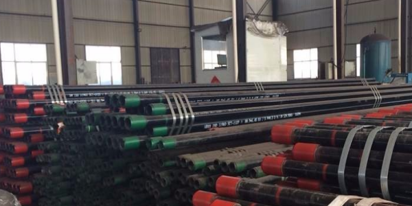
What is Tubing and Tubing Pressure?
First, let's explain what tubing is. Tubing, as the name suggests, is a pipe used to transport oil and gas. In the oil extraction industry, its role extends beyond this. Tubing is a deep-well pipe primarily responsible for transporting fluids, gases, or mixtures from the bottom of the well to the surface during drilling, completion, and production. This means tubing must withstand high pressure from underground, necessitating adequate safety factors in its design and production to prevent safety issues during operation.
Tubing pressure (often referred to as tubing pressure) refers to the pressure of the fluid inside the tubing, specifically the pressure of the fluid at the wellhead. Tubing pressure is the remaining pressure after subtracting the flow pressure, the pressure of the oil-gas mixture column in the well, frictional resistance, and slipping losses. It is measured by a tubing pressure gauge. The level of tubing pressure depends on the flow pressure, which, in turn, is related to the formation pressure. Therefore, tubing pressure reflects the energy level of the well. Pressure data, including the pressure of fluids inside casing and tubing, can be conveniently monitored at the wellhead, usually omitting the "wellhead" part.
What is Casing and Casing Pressure?
In contrast to tubing, casing pipe is also a steel pipe but is primarily used to stabilize the wellbore, prevent wall collapse, and protect the extraction of oil and gas. This requires casing pipe to be designed and produced with consideration of its safety factor under extreme pressures to ensure its safety and stability during operation.
Casing pipe pressure (commonly referred to as casing pressure) is the pressure applied to the casing in the wellbore from the surface. Proper control of casing pressure maintains a good fluid level, thereby improving the well’s high and stable production. For gas wells, multiple layers of casing can be present, with each layer being cemented and protected by annular fluids. Casing pipe pressure is the remaining pressure in the annulus between the casings at the wellhead, and it can be viewed through pressure gauges installed at the Christmas tree.
Differences Between Casing and Tubing Pressure
Comparing casing and tubing, we find that they endure different pressure levels and types of pressure. Generally, tubing needs to withstand higher pressure from underground oil and gas, thus it typically endures higher pressure than casing. On the other hand, while casing also bears pressure, its main role is to stabilize and protect the wellbore, so its pressure rating is usually lower than that of tubing.
Casing pressure is an important parameter in oil well production, and its fluctuations directly impact the well’s productivity, pump efficiency, wax formation, and other factors. During oil well production, when the bottom-hole pressure is lower than the saturation pressure, natural gas separates from the crude oil. The separated gas accumulates in the annular space of the casing, forming casing pressure. Excessive casing pressure can force the fluid level to drop. When the fluid level drops to the depth of the pump intake, gas may enter the deep-well pump, reducing pump efficiency and possibly leading to well shutdown or severe gas lock phenomena.
To effectively control casing pressure, a self-developed plunger-type casing pressure control valve can be used. This valve, installed in the tubing string’s oil nozzle casing, regulates the casing pressure within the specified range based on well data. By changing the spring, the pressure matrix of the valve can be adjusted easily, with simple operation.
Casing and Tubing Pressure Testing
In addition to the basic pressure parameters of casing and tubing, there are other critical pressure testing stages during production. For example, the pressure test of oil casing is a vital step in the manufacturing process, crucial for assessing the overall quality of the steel pipe. Simply put, it involves filling the pipe with water and testing its ability to withstand the specified load without leakage or failure. The water pressure test machine for oil casing detects the pipe's load-bearing capacity. The test load varies by standards. The use of a pressure cylinder to increase pressure is convenient and reliable, equipped with an automatic control system to display load curves in real-time, output test reports, and store test data.
Oil casing can be classified into different steel grades, such as J55, K55, N80, L80, C90, T95, P110, Q125, and V150, based on the strength of the steel itself. Different well conditions and depths require different steel grades for casing. In corrosive environments, the casing must also have corrosion resistance. In complex geological conditions, casing must have resistance to collapse.
Hydraulic Testing Standards and Procedures for Oil Casing and Tubing
Hydraulic testing of oil casing is an essential part of steel pipe production. It functions to test the pipe’s leakage resistance under standard test pressure and stable pressure time and to check the pipe’s radiation and ultrasonic properties under these conditions. The hydraulic test involves three steps: flushing, pressure testing, and water control. The following points should be noted:
According to API-5CT standards:
The static water pressure test strength for oil casing and threaded pipes is based on the lower value of plain-end pipe static water pressure test strength, the maximum static water pressure test strength of the pipe band, and internal pressure leakage resistance, with a maximum standard pressure of 69 MPa. The calculated pressure values are generally rounded to the nearest 0.5 MPa.
The pressure measurement device should be calibrated within 4 months before each use.
If the client has special requirements, higher hydraulic test pressures can be chosen.
If equipment limitations prevent reaching the standard pressure, timely notification to the technical department for process adjustments is necessary.
Key Points for Worker Operation:
Parameter Setting: Set the test pressure and stabilization time according to the size, steel grade, and thread type of the oil casing.
Perform full-length static water tests on each oil casing. The actual test pressure and minimum pressure stabilization time should comply with the process card’s requirements (adjustments may be made based on raw material quality).
During the pressure test, check the seal’s condition and the absence of leaks, ensuring no water leakage is observed at any time.
The test pressure control range for oil casing should be ≥ standard hydraulic test pressure.
Carefully record the static water pressure test data.
In summary, both tubing and casing design and production must fully consider their respective operational environments and pressure endurance characteristics to ensure safe and effective operation during oil and gas extraction. Understanding and comparing the pressures of tubing and casing provides valuable insights into their critical roles and requirements in oil and gas extraction, serving as a fundamental basis for their selection and application. Proper design and application of tubing and casing are essential for the safe operation and efficient extraction of oilfield equipment.


 English
 Español
 بالعربية





 Phone :
  Whatsapp :
  Email :


