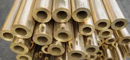
API 5CT Casing Pipe Strength Design: Load Analysis and Oilfield Application Guide
As global oilfield exploration advances and the demand for deeper drilling increases, the structural integrity of API 5CT casing pipes becomes more critical than ever. These essential components in oil and gas wells face extreme axial loads, internal pressure, and external compressive forces during both drilling and production stages. Without a robust strength design, the risk of wellbore failure increases significantly.This article provides a comprehensive overview of the load analysis and strength design principles for oil well casing pipes, offering practical insights into casing material selection, load resistance, and the structural configuration required for high-performance OCTG (Oil Country Tubular Goods) applications.

1. What conditions are required for the strength design of API 5CT casing?
Modern API casing pipes are engineered to withstand multi-dimensional stresses in complex environments such as ultra-deep wells, high-pressure zones, salt rock layers, and unconventional shale formations. With well depths increasing globally, casing pipes must be able to perform reliably under severe mechanical and thermal conditions.The strength design of API 5CT casing must meet three core conditions:
1.1 Internal pressure resistance (implosion strength)
The casing must be able to withstand the pressure of high-pressure oil and gas or liquid on the inner wall in the well.
1.2External pressure resistance (external squeeze strength)
In isolation, cementing and deep well sections, external formation pressure may cause strong squeezing of the casing.
1.3.Tensile strength (breaking load)
After the casing is lowered into the well, it will be subject to tensile stress caused by the depth of the well and must have sufficient tensile resistance.
2. Axial Load on Oil Well Casing Pipe
Axial loads refer to the vertical stress acting along the casing string axis. They typically originate from:
Self-weight of the casing string: Especially significant in deep wells, the weight of the casing pipe exerts continuous downward pressure on lower segments.
Fluid column pressure: Fluids like drilling mud, completion fluids, or injected water/gas exert upward or downward forces along the casing, depending on well operations.
Failure to properly design for axial load can lead to buckling or collapse, endangering the entire well integrity.
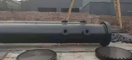
3. External Compression from Geological Formations
External extrusion forces originate from surrounding rock formations and vary depending on factors such as formation pressure and lithology. While soft formations exert minimal stress, salt domes and dense rock layers can generate substantial pressure. In salt formations, time-dependent deformation (creep) further increases compressive forces on the casing. Accurate estimation of formation pressure gradients is essential for selecting the appropriate casing grade and wall thickness to ensure structural integrity.
4. Internal Pressure During Downhole Operations
Internal pressure results from the fluids inside the casing string. Examples include:
Production pressure from oil or gas flow.
Well stimulation operations such as acidizing or fracturing, which can introduce temporary but extremely high internal pressures.
The burst resistance of the casing pipe must be carefully calculated to ensure safe operation.
5. Material Selection for API 5CT Casing Pipe
Material properties significantly influence casing pipe performance under load. Key material considerations include:
Tensile Strength & Yield Strength: Determines the casing’s resistance to pulling and its ability to maintain structural shape under stress.
Hardness: Impacts wear resistance, particularly important in abrasive or high-pressure environments.
Chemical Composition: Affects corrosion resistance and long-term durability. Corrosive wells may require alloy steel or corrosion-resistant casing.
Common grades include J55, N80, L80, and P110, each suited to different well environments.
|
Grade
|
Yield Strength (MPa)
|
Tensile Strength (MPa)
|
|
J55
|
≥ 379
|
≥ 517
|
|
N80
|
≥ 552
|
≥ 689
|
|
L80
|
≥ 552
|
≥ 655
|
|
P110
|
≥ 758
|
≥ 862
|
Wall thickness and size
The wall thickness of the casing directly affects its pressure bearing capacity. Designers need to calculate the required wall thickness based on the strength formula provided by API 5C3 and match the standard specifications, such as:
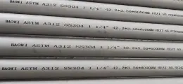
Outer diameter: 4-1/2", 5-1/2", 7", 9-5/8", etc.
Wall thickness: designed according to the usage scenario, generally ranging from 6.45mm to 15mm
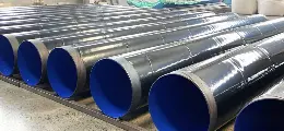
6. Structural Design: Diameter, Thickness, and Thread Connections
A well-engineered casing structure combines optimal diameter, wall thickness, and thread design. Design elements include:
Casing Diameter & Wall Thickness: Larger diameters and thicker walls enhance load-bearing capacity. These must be selected based on well depth, expected pressure, and formation characteristics.
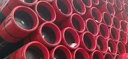
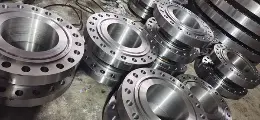
Casing Joints and Couplings: Connections between casing sections are often the weakest point. Threaded and coupled connections, premium threads, and torque shoulder designs help prevent leakage and failure.
Thread Design: Good thread design ensures sealing performance and structural integrity under tensile and torsional loads.
API 5CT P110 Casing Pipe Tensile & Hardness Requirement
|
Group
|
Grade
|
Type
|
Total elongation under load %
|
Yield strength MPa
|
Tensile strength min. MPa
|
Hardness a max.
|
Specified wall thickness mm
|
Allowable hardness variation b HRC
|
|
min.
|
max .
|
|
HRC
|
HBW
|
|
1
|
2
|
3
|
4
|
5
|
6
|
7
|
8
|
9
|
10
|
11
|
|
1
|
H40
|
-
|
0.5
|
276
|
552
|
414
|
-
|
-
|
-
|
-
|
|
J55
|
-
|
0.5
|
379
|
552
|
517
|
-
|
-
|
-
|
-
|
|
K55
|
-
|
0.5
|
379
|
552
|
655
|
-
|
-
|
-
|
-
|
|
N80
|
1
|
0.5
|
552
|
758
|
689
|
-
|
-
|
-
|
-
|
|
N80
|
Q
|
0.5
|
552
|
758
|
689
|
-
|
-
|
-
|
-
|
|
R95
|
-
|
0.5
|
655
|
758
|
724
|
-
|
-
|
-
|
-
|
|
2
|
M65
|
-
|
0.5
|
448
|
586
|
586
|
22
|
235
|
-
|
-
|
|
L80
|
1
|
0.5
|
552
|
655
|
655
|
23
|
241
|
-
|
-
|
|
L80
|
9Cr
|
0.5
|
552
|
655
|
655
|
23
|
241
|
-
|
-
|
|
L80
|
13Cr
|
0.5
|
552
|
655
|
655
|
23
|
241
|
-
|
-
|
|
C90
|
1
|
0.5
|
621
|
724
|
689
|
25.4
|
255
|
≤ 12.70 12.71 to 19.04 19.05 to 25.39 ≥ 25.40
|
3.0 4.0 5.0 6.0
|
|
T95
|
1
|
0.5
|
655
|
758
|
724
|
25.4
|
255
|
≤ 12.70 12.71 to 19.04 19.05 to 25.39 ≥ 25.40
|
3.0 4.0 5.0 6.0
|
|
C110
|
-
|
0.7
|
758
|
828
|
793
|
30
|
286
|
≤ 12.70 12.71 to 19.04 19.05 to 25.39. ≥ 25.40
|
3.0 4.0 5.0 6.0
|
|
3
|
P110
|
-
|
0.6
|
758
|
965
|
862
|
-
|
-
|
-
|
-
|
|
4
|
Q125
|
1
|
0.65
|
862
|
1034
|
931
|
b
|
-
|
≤ 12.70 12.71 to 19.04 ≥ 19.05
|
3.0 4.0 5.0
|
a In case of dispute, laboratory Rockwell C hardness testing shall be used as the referee method.
b No hardness limits are specified, but the maximum variation is restricted in accordance with 7.8 and 7.9 of API Spec. 5CT.
|
At BAOWI, we offer full-scale engineering support and high-quality API 5CT casing pipes to meet your oilfield challenges. Contact us today for specifications, pricing, and customized solutions.

 English
 Español
 بالعربية
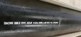
 Phone :
  Whatsapp :
  Email :


