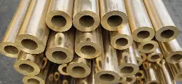
Ductile iron pipe (DIP) has become the main pipe material for buried pipelines in urban water supply, fire protection, and industrial water transmission due to its advantages such as high strength, good toughness, and strong corrosion resistance. However, no matter how reliable the pipe material itself is, the safety of the pipeline system always depends on whether the pressure is controlled - overpressure will cause the pipe to burst, underpressure will affect the water supply, and hidden pressure drops often mean leakage.The pressure gauge on the ductile iron pipe is the only eye on this "underground lifeline".
What Is Ductile Iron Pipe Pressure Rating?
The pressure rating of ductile iron pipes refers to the maximum allowable working pressure (PFA) that a pipe system can safely withstand under normal operating conditions.
In addition, engineers design pressure systems based on:
Internal water pressure
Water hammer effect
Soil load and external forces
Safety factors defined by ISO/EN standards
Unlike burst pressure, pressure rating focuses on long-term safe operation, not failure limits.
Definition of AWWA C150
AWWA C151 (full name: ANSI/AWWA C151/A21.51) is a manufacturing standard for ductile iron pipes developed by the American Water Association. It mainly specifies the dimensions, wall thickness, weight, material properties, testing requirements, and acceptance standards for centrifugally cast ductile iron pressure pipes.Main Requirements of AWWA C151:
|
Item
|
Description
|
|
Material
|
Ductile iron
|
|
Manufacturing Process
|
Centrifugally cast
|
|
Pipe Size Range
|
3 in. to 64 in. (DN80–DN1600)
|
|
Pressure Classes
|
150, 200, 250, 300, 350
|
|
Joint Types
|
Push-on, Mechanical, Flanged
|
|
Testing
|
Hydrostatic pressure test
|
|
Quality Control
|
Inspection and acceptance requirements
|
|
Applications
|
Water supply, wastewater, reclaimed water
|
Ductile Iron Pipe Pressure Rating Chart ( AWWA C150)
The following table shows commonly used pressure classes based on AWWA C150.

In addition to pressure ratings, pipe dimensions are also critical for system design and selection.You can view the full detailed size table and technical specifications here:Ductile Iron Pipe Size Chart and Specifications
This section covers standard DN sizes, wall thickness, weight, and manufacturing standards based on ISO 2531 and EN 545.
Pressure advantages of ductile iron pipes
Given the excellent inherent yield strength of ductile iron pipes, which is 25 times stronger than some commonly used piping materials in the water and wastewater infrastructure market, there is no doubt that ductile iron pipes are the best material to withstand changes or unexpected pressure shocks.
A crucial guarantee of the quality stability of ductile iron pipes is the rigorous factory hydrostatic testing. Each pipe is manufactured according to the American AWWA C151 standard and undergoes a hydrostatic pressure test of at least 500 psi before coating and lining.
This test is extremely rigorous, its main purpose being to proactively identify and address any potential defects. Any internal cracks, pinholes, or structural flaws will be exposed under such high pressure, and substandard products are typically rejected or even scrapped.
In contrast, post-construction piping system hydrostatic testing generally only reaches 150 to 200 psi, far below the factory testing standards. This means that the manufacturing process involves more stringent and extreme inspections, essentially performing an overload safety verification before shipment, ensuring the reliability and safety of the pipelines during long-term use from the outset.
Hydraulic Test of Ductile Iron Pipe
Water pressure testing is an essential step in the installation of ductile iron water supply pipelines. The pressure test verifies the sealing and pressure-bearing capacity of the pipeline system, ensuring that no leaks or pipe bursts occur during later use, and guaranteeing the safety and stability of the water supply.
Before the test, three basic tasks must be completed: Both ends of the pipeline must be tightly sealed with blind flanges; the concrete strength of supports, anchor blocks, and other fixing facilities must reach at least 90% of the design value; and the rubber rings at pipe connections must be fully embedded in the socket, with the exposed length of the joint not exceeding 5mm.
|
Item
|
Technical Requirement
|
|
Working Pressure
|
0.6 MPa / 0.8 MPa / 1.0 MPa (standard grades)
|
|
Test Pressure
|
1.5 × working pressure
|
|
Holding Time
|
Not less than 30 minutes
|
|
Allowable Pressure Drop
|
≤ 0.02 MPa
|
|
Acceptance Standard
|
GB/T 132 “Ductile Iron Pipes, Fittings and Accessories for Water and Gas” or project-specific design requirements
|
|
Special Conditions
|
In high elevation or complex terrain areas, test pressure shall be recalculated separately
|
|
Auxiliary Testing
|
Air pressure test may be added when necessary as supplementary inspection method
|

 English
 Español
 بالعربية
 Phone :
  Whatsapp :
  Email :


