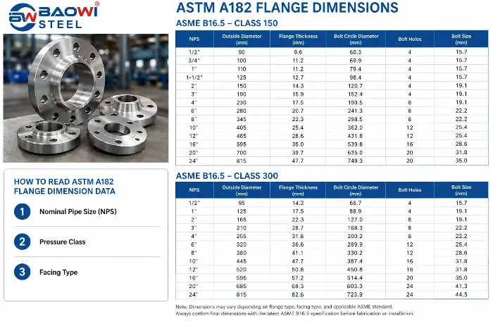
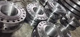
ASTM A182 flanges are widely used in high-pressure and high-temperature piping systems, especially in oil & gas, petrochemical, power generation, and chemical processing industries. However, ASTM A182 itself does not define flange dimensions.
Instead, the dimensional requirements of ASTM A182 forged flanges are mainly specified by ASME B16.5 for NPS 1/2" to 24" and ASME B16.47 for larger sizes up to NPS 60".This guide provides ASTM A182 flange dimensions, including outside diameter, flange thickness, bolt circle diameter, bolt hole size, and weight reference based on common ASME flange standards.
What is ASTM A182?
ASTM A182 is a material specification covering forged or rolled alloy and stainless steel pipe flanges, fittings, valves, and parts. It is commonly applied in industries such as oil & gas, petrochemical, power generation, and chemical processing.
The standard defines:
Mechanical properties
Chemical composition
Heat treatment requirements
Pressure-temperature ratings
However, it does not directly define flange dimensions. These are governed by other standards.
ASTM A182 Flange Dimension Standards
The dimensions of ASTM A182 forged flanges are mainly determined by ASME flange standards.
ASME B16.5 Flange Dimensions
ASME B16.5 covers most standard pipe flanges:
Size range: NPS 1/2" to 24"
Pressure classes: Class 150, 300, 400, 600, 900, 1500, 2500
Facing types:
Raised Face (RF)
Flat Face (FF)
Ring Type Joint (RTJ)
It defines:
Flange outside diameter
Flange thickness
Bolt circle diameter
Number of bolt holes
Bolt hole diameter
Facing dimensions
ASME B16.47 Large Diameter Flange Dimensions
For large diameter piping systems, ASTM A182 flanges normally follow ASME B16.47.
Main range:
|
Standard
|
Size Range
|
Typical Application
|
|
ASME B16.5
|
NPS 1/2"–24"
|
Standard piping systems
|
|
ASME B16.47
|
NPS 26"–60"
|
Large diameter pipelines
|
ASME B16.47 is commonly used in industries such as oil transportation, gas transmission, and large-scale process plants.
Common ASTM A182 Flange Types
|
Flange Type
|
Description
|
Typical Application
|
|
Weld Neck (WN)
|
Long tapered hub
|
High pressure & temperature
|
|
Slip-On (SO)
|
Slides over pipe
|
Low to medium pressure
|
|
Blind (BL)
|
Solid, no bore
|
Pipe end closure
|
|
Socket Weld (SW)
|
Socket connection
|
Small bore, high pressure
|
|
Threaded (TH)
|
Internal threads
|
Non-weld systems
|
ASTM A182 Flange Dimensions Table (ASME B16.5 – Class 150)
Below is a commonly used reference table for Class 150 Weld Neck Flanges:
|
NPS (inches)
|
Outside Diameter (mm)
|
Bolt Circle (mm)
|
Bolt Holes
|
Bolt Size (mm)
|
Thickness (mm)
|
|
1/2
|
90
|
60
|
4
|
16
|
9.6
|
|
1
|
108
|
79
|
4
|
16
|
11.2
|
|
2
|
152
|
120
|
4
|
19
|
14.3
|
|
3
|
190
|
152
|
4
|
19
|
15.9
|
|
4
|
229
|
191
|
8
|
19
|
17.5
|
|
6
|
279
|
241
|
8
|
22
|
20.7
|
|
8
|
343
|
298
|
8
|
22
|
22.3
|
Note: Dimensions may vary depending on flange type, facing type, and applicable ASME standard. Always confirm final dimensions with the latest ASME B16.5 specification before fabrication or installation.
ASTM A182 Flange Dimensions Table (Class 300 Comparison)
Compared with Class 150 flanges, Class 300 ASTM A182 flanges have increased thickness, larger bolt sizes, and stronger bolting arrangements to handle higher pressure applications.
They are commonly selected for:
Petrochemical piping
High-temperature process systems
Refinery equipment
Steam and power generation systems
Typical ASME B16.5 Class 300 weld neck flange dimensions are shown below.
|
Nominal Pipe Size
|
A
|
C
|
G
|
H
|
I
|
J
|
Weight
|
|
inch
|
mm
|
mm
|
mm
|
mm
|
Number of
|
mm
|
mm
|
kg/piece
|
|
Holes
|
|
1/2
|
21.3
|
88.9
|
11.2
|
35. 10
|
4
|
15.7
|
60.45
|
0.42
|
|
3/4
|
26.7
|
98.6
|
12.7
|
42.9
|
4
|
15.7
|
69.85
|
0.61
|
|
1
|
33.4
|
108
|
14.2
|
50.8
|
4
|
15.7
|
79.25
|
0.86
|
|
11/4
|
42.2
|
117.3
|
15.7
|
63.5
|
4
|
15.7
|
88.9
|
1.17
|
|
11/2
|
48.3
|
127
|
17.5
|
73. 15
|
4
|
15.7
|
98.6
|
1.53
|
|
2
|
60.3
|
152.4
|
19. 10
|
91.9
|
4
|
19.1
|
120.7
|
2.42
|
|
2/21
|
73.0
|
177.8
|
22.4
|
104.6
|
4
|
19.1
|
139.7
|
3.94
|
|
3
|
88.9
|
190.5
|
23.9
|
127
|
4
|
19.1
|
152.4
|
4.93
|
|
31/2
|
101.6
|
215.9
|
23.9
|
139.7
|
8
|
19.1
|
177.8
|
6.17
|
|
4
|
114.3
|
228.6
|
23.9
|
157.2
|
8
|
19.1
|
190.5
|
7
|
|
5
|
141.3
|
254
|
23.9
|
185.7
|
8
|
22.4
|
215.9
|
8.63
|
|
6
|
168.3
|
279.4
|
25.4
|
215.9
|
8
|
22.4
|
241.3
|
11.3
|
|
8
|
219.1
|
342.9
|
28.4
|
269.7
|
8
|
22.4
|
298.5
|
19.6
|
|
10
|
273.0
|
406.4
|
30.2
|
323.9
|
12
|
25.4
|
362
|
28.8
|
|
12
|
323.8
|
482.6
|
31.75
|
381
|
12
|
25.4
|
431.8
|
43.2
|
|
14
|
355.6
|
533.4
|
35. 10
|
412.8
|
12
|
28.4
|
476.3
|
58.1
|
|
16
|
406.4
|
596.9
|
36.6
|
469.9
|
16
|
28.4
|
539.8
|
76
|
|
18
|
457.2
|
635
|
39.6
|
533.4
|
16
|
31.75
|
577.9
|
93.7
|
|
20
|
508.0
|
698.5
|
42.9
|
584.2
|
20
|
31.75
|
635
|
122
|
|
24
|
609.6
|
812.8
|
47.8
|
692.2
|
20
|
35.1
|
749.3
|
185
|
ASME B16.5 Class 600 Threaded Flange Dimensions Chart
|
NPS
|
Outside Diameter (mm)
|
Thickness (mm)
|
Bolt Holes
|
Bolt Circle (mm)
|
Approx. Weight (kg)
|
|
1/2"
|
95
|
15.7
|
4
|
22.4
|
0.76
|
|
1"
|
124
|
19.1
|
4
|
26.9
|
1.57
|
|
2"
|
165
|
19.1
|
8
|
36.6
|
3.72
|
|
3"
|
210
|
22.4
|
8
|
46
|
7.29
|
|
4"
|
273
|
25.4
|
8
|
53.8
|
14.88
|
|
6"
|
356
|
28.4
|
12
|
66.5
|
29.68
|
|
8"
|
419
|
31.8
|
12
|
76.2
|
44.47
|
|
10"
|
508
|
35.1
|
16
|
85.9
|
72.06
|
|
12"
|
559
|
35.1
|
20
|
91.9
|
86.25
|
|
16"
|
686
|
41.1
|
20
|
106.4
|
146.16
|
|
20"
|
813
|
44.5
|
24
|
127
|
226.83
|
|
24"
|
940
|
50.8
|
24
|
139.7
|
322.58
|
For complete dimensions including bore diameter, hub diameter, and flange facing dimensions, please refer to the full ASME B16.5 Class 600 threaded flange specification.
ASME B16.5 Class 900 Threaded Flange Dimensions Chart
Dimensions are in millimeters (mm). Approximate weights are in kilograms (kg).
|
NPS
|
Outside Diameter (A)
|
Thickness (I)
|
Bolt Holes
|
Bolt Circle (D)
|
Approx. Weight (kg)
|
|
1/2"
|
121
|
23
|
4
|
31.3
|
1.77
|
|
1"
|
149
|
26
|
4
|
41.1
|
3.44
|
|
2"
|
216
|
26
|
8
|
57.2
|
9.97
|
|
3"
|
241
|
26
|
8
|
53.8
|
11.8
|
|
4"
|
292
|
32
|
8
|
69.9
|
20.19
|
|
6"
|
381
|
32
|
12
|
85.9
|
42.06
|
|
8"
|
470
|
39
|
12
|
101.6
|
71.91
|
|
10"
|
546
|
39
|
16
|
108
|
102.39
|
|
12"
|
610
|
39
|
20
|
117.3
|
135.1
|
|
14"
|
641
|
42
|
20
|
130
|
156.08
|
|
16"
|
705
|
45
|
20
|
133.4
|
189.14
|
|
18"
|
787
|
51
|
20
|
152.4
|
264.26
|
|
20"
|
857
|
54
|
20
|
158.8
|
324.72
|
|
24"
|
1041
|
67
|
20
|
203.2
|
618.5
|
How to Read ASTM A182 Flange Dimension Data ?
When selecting an ASTM A182 flange, engineers should pay attention to more than only pipe size.
The main dimensional factors include:
1. Nominal Pipe Size (NPS)
NPS represents the connection size of the piping system. It does not always equal the actual outside diameter of the pipe.
For example:
NPS 2 pipe has an actual outside diameter of approximately 60.3 mm.
NPS 8 pipe has an actual outside diameter of approximately 219.1 mm.
Therefore, flange selection should always match the piping standard, not only the measured pipe diameter.
2. Pressure Class
Pressure class affects:
Flange thickness
Bolt arrangement
Facing dimensions
Overall flange weight
A Class 600 flange will normally have a heavier and stronger design compared with a Class 150 flange of the same NPS.
3. Facing Type
ASTM A182 flanges may use different facing designs, including:
Raised Face (RF)
Flat Face (FF)
Ring Type Joint (RTJ)
The facing selection depends on sealing requirements, pressure level, and service conditions.
ASTM A182 Flange Dimensions: ASTM A182 vs ASME B16.5
One common misunderstanding is that ASTM A182 determines the complete flange design. In fact, the two standards serve different purposes.
ASTM A182 defines the material requirements for forged stainless steel and alloy steel flanges, including:
Chemical composition
Mechanical properties
Heat treatment requirements
Manufacturing requirements
ASME B16.5 and ASME B16.47 define the actual flange dimensions, including:
Outside diameter (OD)
Flange thickness
Bolt circle diameter (BCD)
Number of bolt holes
Bolt hole diameter
Facing dimensions
This separation allows the same flange dimensions to be used with different ASTM A182 material grades, such as F304, F316, F321, and duplex stainless steel grades.
ASTM A182 F304 vs F316 Flange Dimensions
Many buyers search specifically for:
ASTM A182 F304 flange dimensions
ASTM A182 F316 flange dimensions
The important point is that F304 and F316 flanges usually have the same dimensions when they use the same flange type, NPS size, and pressure class.
The main difference is the material performance.
|
Comparison
|
ASTM A182 F304
|
ASTM A182 F316
|
|
Material Type
|
Austenitic stainless steel
|
Austenitic stainless steel with molybdenum
|
|
Corrosion Resistance
|
Good
|
Excellent
|
|
Chloride Resistance
|
Moderate
|
Higher
|
|
Marine Environment
|
Limited
|
Recommended
|
|
Chemical Processing
|
General use
|
More suitable
|
|
Cost
|
Lower
|
Higher
|
For example:
A Class 300 NPS 6 F304 Weld Neck Flange and a Class 300 NPS 6 F316 Weld Neck Flange will normally follow the same ASME B16.5 dimensional requirements.
The selection mainly depends on:
Corrosion environment
Temperature conditions
Chemical exposure
Project requirements
How to Select the Correct Flange Dimensions ?
Choosing the right ASTM A182 flange involves:
1.Determine pipe size (NPS)
2.Select pressure class (150–2500)
3.Choose flange type (WN, SO, BL)
4.Match material grade (ASTM A182)
5.Verify dimensions using ASME B16.5 tables
6.Confirm compatibility with mating components
What is an ASTM A182 socket weld flange?
An ASTM A182 socket weld flange is a type of flange manufactured using alloy steel, stainless steel, or duplex stainless steel materials specified in the ASTM A182 standard, through a forging process. The connection is achieved by inserting one end of the pipe into the step inside the flange, and welding is then performed on the pipe end and the outside.
Socket weld flanges come in two forms: with neck and without neck. The necked structure offers better rigidity, less welding deformation, and excellent sealing performance, making it suitable for pressure applications ranging from 1.0 to 10.0 MPa. Additionally, Type B flanges for vessels also belong to the socket weld flange category and are commonly used in applications requiring high sealing performance.
Conclusion
ASTM A182 flanges combine high-quality forged materials with standardized dimensions defined by ASME specifications. While ASTM A182 controls material properties, dimensional accuracy depends on standards like ASME B16.5 and B16.47. Understanding these relationships is essential for safe, efficient, and long-lasting piping systems.
By carefully selecting flange type, pressure class, and material grade—and verifying dimensions against recognized standards—engineers and buyers can ensure optimal performance and reliability in demanding industrial applications.
Related ASTM A182 Resources
For more information about ASTM A182 forged flanges, see:
ASTM A182 F304 vs F316 Flange Comparison
Socket Weld Flange Guide
ASME B16.5 vs ASME B16.47 Flange Difference
ASTM A182 Flange Pressure Rating Chart

 English
 Español
 بالعربية


 Phone :
  Whatsapp :
  Email :


